It was during Fab Academy where I first learnt about electronic prototyping and mechanical design. This was a huge learning curve for me, but very satisfying. I learnt how to write Arduino code, control DC and stepper motors, receive data from sensors and to physically interact with Grasshopper. While working on my final project I managed to get to the point where I was able to build an Arduino from scratch.
Here I have recorded a few of the projects I made.
FabISP
Microcontrollers come blank with no information as to what the chip should do. When we create a new board we need to flash basic information onto it so we can access it from a computer, this includes even being able to be accesed via USB. The FabISP (Fab in system programmer) allows us to program blank AVR microcontrollers with this basic information.
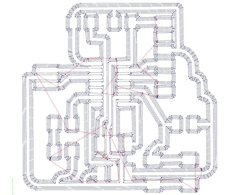
I was introduced to a new machine - the Roland SRM-20 - and an opensource program to control it called FabModules. FabModules uses .png files to create the code and it cuts the black area and leaves the white.
This was my first time soldering in a long time. The pins on this board are tiny and seeing some of the microcontrollers, they only get smaller. I managed to pass my 'smoke test' (if there is a short the board may begin to heat up to much) and successfully program my FabISP.
Electroncis Design
This project involved taking a simple board with a microcontroller and redesigning it to have an LED powered by a switch. For this I used a program called Eagle, which allows you to draw traces
Embedded Programming
Using the ATTiny44 microcontroller datasheet, I was able to specify which pin would be the input and output for the button and LED respectively.
With this information I was able to write the arduino code that allowed me to turn the LED on and off.
First however, I had to 'burn the bootloader', which programmed the pins on the microcontoller.
Stepper motor
More on this project can be found here
This project required the control on 3 stepper motors to rotate a platform and move a pair of arms up and down. For this I used the CNC3.5 Arduino motor shield and Pololu drivers. The allowed the use of a specific library which gave much easier control of the steppers.
Outputs
This project involved connecting an arduino to two DC motors via an H-bridge. The H-bridge has inputs which when in a certain combination of states makes the motor go one way or the other or stop. It also allows the motors to be controlled by a higher voltage than the Arduino microcontroller can manage.
I used a program called Fritzing to help understand my connections and the Arduino IDE to program my arduino.
Inputs
I wanted to control my two DC motors using a joystick. The aim of this was to create a remote controlled vehicle. The wiring for this setup is well documented, but I needed to translate the different analogue X and Y inputs into a left and right motor value i.e. I want the vehicle to turn left, the right motor will go faster than the left etc..
I described each of the main conditions of the joystick position and managed to work out the maths required to alter the different motor speed. For this example I used 4 LEDs to show clockwise and anticlockwise motion of each motor.
Radio
Finally To control the motors remotely of the joystick I used the NRF24L01 transceiver module. It was a great module to set up and truly satisfying when you start receiving data from across the room.
With this module I learnt a lot about SPI communication, power circuitry and had plenty of practice soldering while creating a prototype board for this to work.


